
Attraction mode,
http://www.energyscienceforum.com/members/john_bedini.html
http://www.energyscienceforum.com/showthread.php?t=1232&p=11358#post11358
 using a dremel to ged rid of the enamel

got blank ends in few minutes, easily ;o)
when coil fires, a magnetic south pole should be established at the top of the coil.
the prewound coil has two ends,
one is twisted and cutted,
the other end has loose single wires
This predefines, which end is dedicated for which connection…
The twisted and cutted end will be the end that goes to the „Primary +“ rail.
The loose end with single wire ends will go to the circuit board binding posts.
The binding posts are connected to transistors Collector pin, that switches along the Emitter to the „Primary -“ terminal.
The binding posts also goes along the diodes beside themselves, to the „Charge +“.
With that information, we know which end of the coil is connected to battery „+“ terminal, and which end goes to a battery „-“ terminal.

With a test setup, an compass positioned above the coils core, and small batteries AA type in serie or similar low voltage source, we can test, where the south pole appears.
When we have located it, we turn the coil, so that this south pole appears at the top.
The core welding rods are longer as the coils height, and so they should be used extended at the top bottom( i get not enough trigger volts/milliamps when rods are extended at the top) of the coil.
http://www.free-energy.ws/images/6coil7.jpg
now we are ready to bring coil in position under the wheel,
Important hint:
isolate your trigger wire carefully,
keep them away from the nearby powerwindings!!!..
i had such an accident, the transistors and heatsinks got warm
where my two test powerwindings where connected at.
And the diodes at Base (between transistor base and „Primary -„) were destroyed.. guessed at first.
At all 8 transitors, i thought !
Dont know yet, if the two or all transistors are shredded,
can not measure while they are soldered.
I had to desolder the destroyed diodes and replace them with new ones.
Solutions: use luster clamps/Lüsterklemmen…or at least use isolation tape..
But for all electronic components its valid to say, you can not check measure them, while they are soldered into the circuits, because the testcurrent will flow not the way as it should.. it depends strongly on the circuit.
These diodes can block till 1000Volts, so they could not get destroyed while 12V in reverse bias/blocking mode, but when 12V high amperage is running in condutive mode.. they can get destroyed. „You can measure it with digitalmeter, measure both directions.. if the diode is in both ways conductive, it is wrecked“ << this is not true for all cases, read bold text above.
A two volts trigger test with an signalgenerator, showed very slightly glimming neons.. with triggersignal in one direction and reverse direction too, the diodes are conductive, so the trigger current goes „partialy through the diode and the transitor Base to Emitter“?
Till now i dont understand this glimming effect of the neons.
For possibility of easy replacement and testing the transistors,
it would be great to use transistor SIP3 sockets between board and transistor.
http://de.farnell.com/te-connectivity-amp/382437-1/sip-socket-3pos-through-hole/dp/4964056
http://www.te.com/catalog/pn/en/382437-1?RQPN=382437-1 ( << view 3D PDF !)
http://de.mouser.com/ProductDetail/TE-Connectivity/382437-1/?qs=%2fha2pyFadugL7evFaAWIvO8sIBeAR1zpuYk3V%2f3kIQIukURLdUWfcw%3d%3d
Tip of Teslagenx Team: its not recommended, do not use sockets, because of oxidation of contacts!
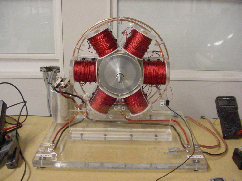
My wheel with the superpole config,
could be to weak.. doesnt induce enough trigger volts/milliamps,
so i add additional magnets (at 90degree) at these superpole mags,
so i have a standard bedini wheel type, for starting tests..
Now i connect the trigger wire ends to an digital-multimeter/oscilloscope to measures the induced trigger volts/milliamps, when the wheel gets hand cranked for starting.
The values are:
My old coils measure: (superpoles attraction mode was already difficult to tune in to get the machine in rotation, trigger wire was tighter to the core, „better“ than the 8+1 wire coil)
Here some picture from oscilloscope, measuring trigger wires only
– twisted 8wire coil from teslagenx, core welding rods, extended rods at top, superpole magnets
– my old coil, with welding rod core but not top extended core, superpole magnets
– my old coil, with welding rod core but not top extended core, standard magnets
– twisted 8wire coil from teslagenx, core welding rods, extended rods at bottom, superpole magnets
– twisted 8wire coil from teslagenx, core welding rods, extended rods at bottom, standard magnets
As expected, the superpole magnets do induce much less current into the trigger coil.
The extended rods at the top do also induce less current into the trigger coil.
So at the end, use standard magnet configuration, no superpole sandwiches, and let the welding rods extend at the bottom of the coil.
So you will get for sure enough trigger volts/milliamps to trigger the circuit, transitors.
2013/11/20 i got the SG8 board to run.. with first 4 strands, have some trouble to hold wheel on rpms.. have to check if its repulsion or attraction mode.. i guess repulsion..
charge battery is strongly affected, operating current draw under 400 milliamps
# # # # # #
Connecting procedure:
always start to connect the charge battery, end with disconnect charge battery
1. Battery „Charge -“ to Battery „Primary +“
2. Battery „Charge +“ to SG8 kit „Charge +“
3. Battery „Primary -“ to SG8 kit „Primary -“
for attraction mode:
4. Trigger Coil (Top,End) to SG8 kit Trigger terminal (with or without the 10W12R)
5. Trigger Coil (Bottom,Start) to SG8 kit „Primary -“
6. Power Coil (Top,End) to Battery „Primary +“ ( = Battery „Charge -„)
7. Power Coil (Bottom,Start) to SG8 kit binding posts
# # # # # #


